 Skip to content
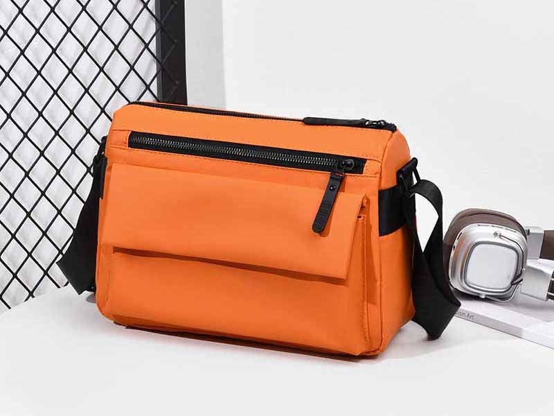
A zipper can look perfectly acceptable on a development sample and still become one of the first components to fail after the finished bag enters regular use. The reason is that real users rarely operate zippers under controlled laboratory conditions. They pull upward, sideways, around curves, against overfilled compartments, while wearing gloves, or through oversized branded pullers that change the leverage applied to the slider. A smooth-looking zipper therefore says very little about how its slider, bridge, pull tab, locking mechanism, and surrounding bag structure will respond when the closure is actually loaded.
To test zipper slider and puller strength, the assembled slider is secured in a suitable fixture and the puller is loaded in a defined direction while force and failure behavior are recorded. A useful evaluation may include straight pull-off, angular pull-off, twist resistance, slider deformation and recovery, lock holding, and repeated cycling. The correct method and acceptance level depend on zipper construction, puller design, bag structure, product use, customer specification, and the applicable test method.
This distinction matters because zipper failures rarely happen in one simple way. A puller can stay attached while the slider bridge bends. A slider can survive a strong straight pull but deform during twisting. A zipper that works perfectly when held straight can become difficult after it is sewn around a tight EVA case corner or through several layers of foam, lining, and binding. The most useful question is therefore not simply whether a zipper is “strong,” but which part is being loaded, how it is being loaded, what fails first, and whether that failure would create a real problem in the finished bag.
What Is Zipper Slider and Puller Strength?

Zipper slider and puller strength describes how well the slider body, pull tab, bridge, attachment point, and locking parts resist pulling, twisting, deformation, and separation. It is not one universal strength number. Reliable evaluation separates several failure modes because the puller can remain attached while the slider deforms, the connector opens, or the locking mechanism stops performing correctly.
Slider Strength
The slider is the moving mechanical component that brings zipper elements together or separates them as it travels along the chain. Its strength depends on material, wall thickness, casting or forming quality, internal geometry, bridge design, manufacturing tolerance, and compatibility with the zipper chain. During real bag use, the slider receives force from several directions at the same time because the hand pulls the tab while zipper resistance and pressure from the bag panels act through the chain.
A slider therefore does not need to fracture completely before it should be considered damaged. Small permanent dimensional changes can alter the gap between the upper and lower plates of the slider. Once this geometry changes, the zipper elements may no longer engage consistently, the zipper can begin separating behind the slider, or operating resistance may increase significantly. In some cases, a customer may describe the problem as “the zipper keeps opening,” although the root cause is actually deformation of the slider rather than failure of the chain itself.
ASTM D2061 treats slider deflection, compression resistance, puller attachment, twisting behavior, and slider-lock holding as separate mechanical properties. This is a useful engineering approach because it prevents a single strong test value from hiding a weakness elsewhere in the assembly. A slider that survives a direct pull may still perform poorly when compressed, twisted, or exposed to continuous opening pressure.
The application also matters. A #3 zipper used on a small inside pocket normally experiences very different forces from a larger zipper used on a travel bag, cooler bag, tool bag, or structured case. Increasing zipper size can improve the overall capacity of a closure system, but nominal size alone does not guarantee adequate slider strength. Slider material, puller geometry, zipper chain quality, and finished-product loading still need to be considered together.
Puller Attachment Strength
Puller attachment strength refers to how securely the pull tab remains connected to the slider when mechanical load is applied. Although the connection area is relatively small, it carries nearly every operating force that the user sends into the zipper. The bridge, attachment loop, hole, or connector therefore becomes a concentrated stress point, especially when operating resistance is high.
Standard zipper pullers are usually short and compact, keeping the user’s force relatively close to the slider body. Custom pullers can behave differently. A long zinc-alloy logo pull, molded rubber pull, leather extension, webbing loop, or decorative metal tab changes the distance, direction, and stiffness through which force is transferred. A puller that looks premium and feels comfortable may still introduce more bending moment into the bridge than the slider was originally designed to handle.
This is why branded pullers should be evaluated as functional hardware rather than only as decorative accessories. Important dimensions include overall length, thickness around the attachment hole, hole diameter, edge radius, material, weight, and distance from the attachment point to the user’s gripping area. Small changes in any of these features can affect stress concentration and long-term performance.
A useful inspection also looks beyond complete detachment. The bridge may begin opening, the puller hole may elongate, the attachment point may rotate permanently, plating can crack, or the slider can lose smooth operation after a strong load. These intermediate failure signs are often more valuable during development because they reveal the weak point before a complete field failure occurs.
For custom bag programs, zipper inspection may include slider condition, custom puller quality, opening smoothness, zipper strength, puller logo, and surface treatment. The documented inspection process also identifies puller breakage, sticking, zipper opening, incorrect direction, and custom-puller finish problems as risks that should be detected before components continue into bulk production.
Pull-Off, Twist, and Lock Strength
Pull-off, angular pull-off, twist resistance, slider deformation, and lock holding describe different mechanical problems, so they should never be compressed into one generic “zipper strength” figure. Straight pull-off looks at whether the puller remains attached during direct tensile loading. Angular pull-off changes the direction of the same basic force, while twist testing applies rotational stress. Lock-strength testing evaluates whether a locking slider stays in place while force acts through the zipper chain.
A slider can perform well in one test and poorly in another because different tests concentrate stress in different locations. A rigid metal puller may survive a high straight pull while creating much greater stress at the bridge when twisted sideways. A strong puller attachment also says little about whether the slider body maintains its geometry, and a robust slider does not automatically mean the lock mechanism can resist movement when an overfilled bag creates continuous opening force.
Recording the failure location is therefore as important as recording the maximum force. Typical observations include puller fracture, attachment-loop opening, bridge deformation, slider-body spreading, permanent rotation, lock failure, surface cracking, or loss of smooth operation after testing. A result such as “170 N” provides limited information unless the report also states what happened at that force and whether the component remained functional afterward.
| Strength Property | Main Load | What It Reveals | Typical Failure |
|---|---|---|---|
| Straight pull-off | Tensile | Puller attachment integrity | Puller detaches or bridge opens |
| Angular pull-off | Off-axis tensile | Strength under sideways loading | Uneven connector deformation |
| Twist resistance | Rotational | Resistance to torsional misuse | Puller twists or connector opens |
| Slider deflection | Compression/deformation | Slider geometry stability | Permanent body deformation |
| Lock holding | Holding load | Slider locking ability | Slider moves despite locking |
| Cycling durability | Repeated operation | Long-term functional stability | Looseness, sticking, wear |
These properties help product teams understand what a zipper assembly can and cannot tolerate. Instead of describing a zipper as simply “strong,” the test results can show which load direction creates the greatest risk, whether the puller or slider is the weaker component, and whether the product remains operable after a defined mechanical challenge.
Which Tests Measure Slider and Puller Strength?

The most useful tests include straight pull-off, angular pull-off, twist or torsional resistance, slider deformation, lock holding, and repeated cycling. The appropriate combination depends on zipper type, puller construction, bag geometry, operating frequency, and probable failure mode. Testing should reproduce realistic risks instead of running every available method without considering how the zipper will actually be used.
Pull-Off Testing
Pull-off testing is one of the clearest methods for evaluating the connection between the zipper puller and slider body. The slider is secured in a controlled fixture, the puller is held in a defined position, and tensile force is applied until the component reaches a specified proof load or fails. The highest load and the physical failure behavior are then recorded.
Repeatability is essential. Different samples should use the same slider specification, puller version, fixture, loading direction, speed, and test condition. If one sample is clamped differently from another, the measured difference may come from the fixture rather than the product. A grip that crushes the slider body can artificially lower the result, while a puller that slips in the upper fixture can prevent the true component limit from being reached.
The endpoint also needs to be defined before testing. Some projects use a proof load, where the component must survive a specified force without unacceptable damage. Other evaluations continue until fracture or separation to identify ultimate failure strength. Either approach can be useful, but they answer different questions and should not be mixed casually in the same result table.
For custom pullers, pull-off testing becomes especially valuable because changing the geometry or material can alter the entire load path. A heavier or longer rigid puller transfers force differently from a flexible cord extension. A branded puller may therefore require its own validation even when the underlying zipper chain and slider family have already been used successfully on another product.
Angular Pull Testing
Angular pull testing evaluates the puller connection when force is applied away from a straight axis. This more closely reflects many real bag-use situations because users often pull zippers upward or sideways, especially when the zipper is recessed, installed around a curve, partially obstructed, or under pressure from the contents inside the bag.
YKK publicly shows slider-tab pull-off testing at both 90° and 45°, demonstrating that loading direction can be treated as a controlled test variable rather than simply judged by hand. These angles are useful examples of how a zipper supplier may structure testing, although they should not automatically be interpreted as universal acceptance requirements for every zipper or every bag program.
The effect of loading direction becomes more important when the puller is long and rigid. The farther the hand force acts from the slider bridge, the greater the mechanical moment that can be created when the user pulls sideways. This does not mean that long metal pullers are inherently unsuitable, but their geometry changes the mechanical condition and should therefore be considered during development.
Angular testing is especially relevant for structured luggage, EVA cases, insulated cooler bags, camera cases, and other products where the zipper follows corners or thick panel constructions. If the finished product naturally encourages off-axis pulling, testing only in a perfect straight direction may provide an incomplete view of the risk.
Twist Resistance
Twist testing focuses on rotational loading rather than direct separation. Users can twist pullers when opening bags quickly, grabbing a zipper from an awkward angle, operating the closure with gloves, or pulling two sliders toward each other. Large decorative pullers can make this effect more pronounced because their rigid shape transfers rotational force directly into the attachment point.
The useful observations include whether the puller rotates permanently, the connection loop opens, the slider bridge bends, the puller fractures, or the slider continues to work properly afterward. A component may survive the applied torque without breaking but still become unacceptable if it no longer lies flat, rubs against the bag surface, or creates rough operation.
Puller material plays an important role. Flexible fabric or cord pullers can bend and partially align themselves with the direction of the hand, reducing the torsional load transmitted directly to the slider. A rigid zinc-alloy or molded plastic puller cannot absorb movement in the same way and may concentrate force more strongly at the attachment bridge.
For this reason, comparing only puller length or appearance is not enough. Two pullers with similar dimensions can behave differently if one is flexible and the other is rigid, or if one has a thin attachment section and another uses a thicker reinforced hole. Twist behavior should be assessed as part of the complete mechanical design.
Slider and Lock Evaluation
Slider deformation and lock holding evaluate properties that a puller test alone cannot reveal. A slider may retain the pull tab yet change shape enough to affect zipper function, while a locking slider can remain visually intact but allow unintended movement along the chain.
Deflection evaluation looks at how the slider geometry responds to a defined force and whether it returns close to its original dimensions after the force is removed. Permanent deformation is particularly important because the relationship between the slider mouth and zipper elements determines how reliably the chain engages.
Lock evaluation becomes relevant when the slider contains an automatic or semi-automatic locking mechanism. When the pull tab is released, the lock is intended to resist movement. If the lock is weak, pressure from an overfilled compartment can allow the slider to creep even though the puller and slider body have not fractured.
This can create confusing field complaints. A customer may report that “the zipper opens by itself,” while the chain, puller, and slider remain visually intact. The real issue may be insufficient holding performance of the locking mechanism under the load created by the finished bag.
For products with meaningful closure pressure, slider strength should therefore be reviewed as a combination of dimensional stability, puller attachment, operating behavior, and locking performance rather than one isolated mechanical test.
How Is a Zipper Strength Test Performed?

A controlled zipper-strength test requires a defined sample, appropriate fixture, calibrated force measurement, controlled loading direction, and predetermined failure criterion. The slider must be restrained without creating artificial damage, and the puller should be loaded consistently. Reliable reporting records peak load, deformation, failure location, and post-test function so results can be compared between samples, suppliers, and production batches.
Equipment and Setup
A universal tensile testing machine is commonly used for pull-off testing because it can apply load at a controlled rate and continuously record force. The load-cell range should match the expected test level closely enough to maintain useful measurement resolution. Using an extremely high-capacity load cell for a relatively small zipper component can reduce sensitivity, while a load cell that operates near its maximum range may create reliability or safety concerns.
Fixtures are just as important as the machine itself. The lower fixture should hold the slider or zipper assembly firmly without crushing the component, changing its geometry, or concentrating stress in a location that would not normally receive load. The upper fixture must grip the puller securely without allowing slippage, cutting flexible materials, or artificially reinforcing the weak area.
Different puller constructions may require different gripping approaches. Flat metal tabs can often be held directly, while cord, webbing, leather, or molded pullers may need pins, loops, wraps, or custom fixtures. The goal is to introduce force through the intended load path rather than through an arbitrary clamping point.
A useful setup record normally includes the test-machine identification, load-cell capacity, fixture description, loading speed, sample orientation, pulling angle, sample quantity, and defined endpoint. When a customer specification or recognized standard is used, the test configuration should follow that method rather than being modified simply to produce a higher result.
Loading Direction
Loading direction has a major effect on zipper slider and puller performance. Straight tensile loading gives a useful baseline, but it rarely represents every force that a finished bag will create. Zippers installed on different products can be pulled horizontally, vertically, sideways, or through continuously changing angles as the slider travels around a curve.
For a straight pull-off evaluation, the puller should be aligned consistently with the intended test method. For angular testing, the loading angle should be intentionally established and maintained. Allowing the puller to swing randomly during the test makes it much harder to compare results between samples.
Finished-product design provides useful guidance for selecting the most relevant direction. A straight top opening on a simple tote usually creates a more predictable pull path than the zipper around a structured camera case or insulated cooler bag. Thick foam, binding, multiple seam layers, and tight radii can all increase operating resistance and encourage the user to pull at less favorable angles.
The documented development process for zipper problems considers zipper specification, pattern curvature, material thickness, sewing pressure, slider size, and the inherently higher resistance of some waterproof constructions. This prevents teams from automatically blaming the zipper when the installed structure may be creating the difficulty.
Recording Test Results
Peak force should be reported using the unit required by the applicable standard or project specification. Newtowns are commonly used in technical reporting. For reference, 1 kilogram-force is approximately 9.81 N, while 1 pound-force is approximately 4.45 N. These conversions can help interpret legacy requirements, but production documents should normally maintain one consistent unit to reduce confusion.
Individual results are more informative than an average alone because zipper parts can fail in different ways even when the maximum forces appear similar. A group of samples may produce a narrow force range while showing puller fracture, bridge deformation, connector opening, or permanent slider distortion. The mechanical solution for each of those problems would be different.
| Sample | Peak Load | Failure Mode | Post-Test Condition |
|---|---|---|---|
| 1 | 162 N | Puller hole elongated | Slider still operable |
| 2 | 171 N | Bridge deformation | Rough operation |
| 3 | 168 N | Puller fractured | Slider operable |
| 4 | 174 N | Connector opened | Assembly failed |
| 5 | 169 N | Bridge deformation | Assembly failed |
The values in this table illustrate how results can be documented; they should not be treated as universal pass requirements. A project should use its specified test method and acceptance level. Photographs of failed specimens are also useful because they show the precise damage location, making supplier discussions and corrective-action analysis much clearer than a spreadsheet containing only numerical values.
Failure Classification
Failure classification converts test results into practical engineering information. Typical slider and puller failures include puller fracture, hole elongation, connector opening, bridge bending, slider-body spreading, lock failure, permanent rotation, coating damage, and loss of smooth operation after loading.
The first meaningful loss of function may be more important than the ultimate breaking point. For example, a slider may begin deforming at a lower load and finally separate only after significantly more force is applied. Reporting only the final separation value can hide the point at which the zipper already became unsuitable for normal use.
Patterns across several samples should also be reviewed. If most samples fail through the same bridge location, the problem may relate to slider geometry, wall thickness, or material. Consistent puller fracture can point toward insufficient puller section thickness, casting defects, or stress concentration around the attachment hole. Mixed failures can indicate that several parts of the assembly have similar strength levels.
The objective is not automatically to make every component thicker or heavier. Better geometry, improved material consistency, a different slider-puller connection, or a more suitable zipper specification may solve the weakness with less added cost and weight.
Which Standards Apply to Zipper Strength Testing?

ASTM D2061 is widely used for strength testing of zippers and zipper parts, while ASTM D2062 addresses operability. Customer and brand specifications may add their own acceptance requirements. The method, sample condition, force target, and failure rules should be established before testing so that results are evaluated consistently rather than adjusted afterward to make a component appear acceptable.
ASTM D2061
ASTM D2061 covers multiple strength properties of complete zippers and individual zipper components. Relevant slider and puller methods include pull-off resistance, angular pull-off, twist resistance, torsional resistance, slider deflection and recovery, cushioned compression, and slider-lock holding strength.
An especially useful principle in the standard is that a single test cannot determine whether a zipper is suitable for every final application. A zipper assembly contains several interacting parts, and different end uses expose those parts to different combinations of load, operating frequency, direction, environmental conditions, and closure pressure.
This is directly relevant to bag development. A lightweight zipper used on an internal cosmetic pocket may mainly need reliable opening and basic attachment strength, while a closure on a travel bag, tool bag, outdoor case, or frequently opened backpack can experience significantly more demanding mechanical conditions.
ASTM methods create a shared technical language for laboratories, manufacturers, and product teams, but they do not replace a product specification. A useful project document still needs to identify the zipper type, slider model, puller revision, sample quantity, test method, acceptance value, and failure criteria.
Simply stating that a zipper is “ASTM tested” is less useful than documenting exactly which property was tested, under which method, and what result was required.
ASTM D2062
ASTM D2062 addresses zipper operability rather than the component-strength properties covered by D2061. Operability focuses on functions such as opening, closing, sticking at stops, and separator operation. The distinction matters because mechanical strength and user experience are related but not interchangeable.
A zipper can use a strong slider-puller connection and still be uncomfortable to operate if the chain, slider fit, waterproof coating, curvature, or sewing geometry creates excessive resistance. Another zipper may feel extremely smooth during hand evaluation while using a puller connection that becomes vulnerable under higher mechanical load.
For high-use bag categories, both performance dimensions often matter. Travel bags, backpacks, medical organizers, camera cases, cooler bags, and tool bags may be opened repeatedly, making smooth operation important throughout the product life. Strength testing helps establish resistance to mechanical damage, while cycling and operability evaluation show whether the closure continues functioning after repeated use.
The documented testing framework also includes zipper cycling for evaluating repeated opening, sticking, slider loosening, zipper opening, coating wear, and behavior through curved sections.
Separating these questions prevents a common mistake: approving a zipper simply because it feels smooth during a few manual cycles or approving it only because one component achieved a high pull-off value.
Brand Specifications
Established product programs often combine recognized test methods with internal brand requirements. These specifications may define minimum performance, sample quantity, conditioning, acceptable deformation, approved test laboratories, or different targets for individual product families.
Brand specifications become particularly valuable when the same closure system is expected to remain consistent over several seasons or repeat orders. A clearly documented requirement allows sourcing, development, quality, and manufacturing teams to evaluate the component against the same reference instead of relying on subjective descriptions such as “heavy duty,” “premium,” or “strong metal zipper.”
The component description also needs enough detail to prevent unintentional substitution. “Black #5 zipper” can describe many combinations of chain, tape, slider, puller, finish, and supplier. A better specification identifies the zipper family, slider model, puller drawing or revision, coating or plating, color reference, and the test requirement that matters for the intended product.
Custom pullers should receive particular attention because small drawing changes can alter their mechanical behavior. A supplier may deepen a logo, enlarge an attachment hole, reduce material thickness, or switch alloy while leaving the overall appearance almost unchanged. Maintaining both a released drawing and an approved physical sample helps control these details.
Acceptance Criteria
There is no responsible universal statement that every zipper slider or puller used on a bag must meet one identical newton value. Acceptance depends on zipper construction, slider design, puller geometry, intended product use, customer requirement, and the precise test method.
This is why generic statements such as “all quality zipper pullers must withstand 300 N” should be treated cautiously unless they are linked to a specific specification or product program. A number without method, sample condition, or failure definition can create false confidence.
The documented quality framework states that performance testing can be arranged according to product requirements and customer standards and specifically warns against claiming that every item receives tensile testing when that is not actually the case. It also separates internal inspection, destructive testing, AQL inspection, and third-party support rather than presenting them as the same process.
A useful acceptance rule may include more than one condition:
- Specified test method
- Required proof or failure load
- Maximum allowed permanent deformation
- No puller detachment
- No unacceptable bridge opening
- Slider remains operable
- Lock remains functional
- Defined sample quantity
- Defined allowable failures
- Test report or record requirement
These criteria make decisions repeatable and give the manufacturer a clear target before production begins instead of creating arguments after a failure has already occurred.
How Do Bag Designs Affect Zipper Strength Requirements?
Bag structure directly changes how the zipper is loaded. Zipper location, compartment pressure, curve radius, material thickness, seam construction, foam, waterproof coatings, puller geometry, and access direction can all affect operating force. Component testing should therefore be combined with assembled-bag evaluation because a suitable loose zipper can behave differently once it is sewn into a structured product.
Zipper Location
A zipper on a small inside pocket usually experiences much less mechanical stress than the main closure of a travel bag. Internal pockets normally carry little outward pressure, while main compartments may be packed tightly enough for clothing, tools, equipment, or accessories to push continuously against the zipper chain.
Location also changes the way users operate the closure. A backpack front pocket may be opened with one hand while the bag remains on the shoulder. A top-opening travel bag may be pulled upward. A structured case may require the slider to move around several corners. Tool bags can be handled with gloves and exposed to dust or debris that increases resistance.
When resistance increases, users naturally pull harder. The additional hand force is transmitted through the puller, slider, zipper elements, tape, seam, and surrounding panels. A useful design review therefore follows this complete load path rather than treating the puller as an isolated part.
If the zipper chain is undersized, replacing the puller alone may not solve the weakness. If the zipper route creates excessive friction, installing a heavier slider can leave the underlying problem unchanged. Closure design works best when zipper specification, slider size, puller geometry, sewing structure, and product loading are considered together.
Curved Zipper Paths
Curved openings are a common reason a zipper that appears acceptable as a loose component becomes difficult after sewing. As the slider travels around a curve, the zipper tape and elements must change direction while remaining correctly positioned inside the slider. Tight curves, thick seam assemblies, and stiff panels can increase the resistance required to move the slider.
Structured cases create particularly demanding conditions because several layers may meet at the zipper seam. EVA shells, foam, lining, piping, binding, coating, or reinforcement can push against the zipper tape and reduce its freedom to bend naturally. Water-resistant and waterproof zipper constructions may also feel tighter than standard coil zippers, making pattern geometry even more important.
There is no single universal minimum curve radius that applies to every bag zipper. The practical limit depends on zipper size, tape flexibility, surrounding material thickness, slider construction, and sewing method. The most reliable approach is to assess the actual assembled sample rather than depend only on a drawing.
The documented zipper inspection process includes incoming open-close checking, first-piece assembly testing, special attention to curved locations, confirmation of zipper direction, and bulk smoothness inspection.
When a curved zipper is difficult to operate, the root cause may involve zipper size, slider geometry, sewing pressure, seam allowance, paper-pattern radius, foam thickness, or coating rather than a single defective component.
Custom Puller Geometry
Custom pullers provide a visible branding opportunity and can make a zipper easier to grip, but they also change the mechanical relationship between the hand and the slider. Length, rigidity, weight, hole dimensions, edge geometry, and material determine how directly force is transferred into the slider bridge.
A longer rigid puller increases the distance between the user’s hand and the attachment point. When the user pulls sideways, this longer lever arm can create more bending moment at the bridge. A short flexible cord behaves differently because it can bend and realign itself with the direction of force, reducing some of the torsional loading transmitted to the slider.
Material further changes the behavior. Zinc alloy, stainless steel, aluminum, plastic, rubber, silicone, leather, cord, and webbing each have different stiffness, weight, and wear characteristics. A puller that performs well in one material should not automatically be assumed to behave the same after conversion to another.
Useful design checks include the thickness around the attachment hole, distance from the hole to the gripping area, edge radius, overall mass, logo depth, surface finish, and clearance around neighboring parts. A thin attachment section can fracture, a sharp-edged hole can wear against the bridge, and an oversized puller can collide with another slider in a double-slider design.
Mechanical and visual approval should therefore happen together. A custom puller is both a brand element and a working part of the zipper system.
High-Risk Bag Types
Some bag categories justify more detailed zipper verification because they involve higher operating frequency, stronger compartment pressure, demanding environments, or greater consequences when the closure fails.
Travel bags, backpacks, tool bags, cooler bags, camera bags, delivery bags, medical organizers, pet carriers, and structured EVA cases are typical examples. The documented zipper-testing scope includes several of these applications and checks smooth operation, zipper opening, slider security, curved-route behavior, and double-slider performance.
A practical product assessment can compare several risk factors rather than classifying products only by size.
| Risk Factor | Lower-Risk Condition | Higher-Risk Condition |
|---|---|---|
| Opening frequency | Occasional storage pouch | Daily-access backpack |
| Compartment pressure | Flat document pocket | Packed travel bag |
| Zipper route | Straight opening | Multi-curve structured case |
| Puller type | Short flexible pull | Long rigid metal pull |
| Environment | Indoor cosmetic pouch | Outdoor tool bag |
| Closure resistance | Standard coil zipper | Tight coated zipper |
| Failure impact | Minor inconvenience | Contents exposed or lost |
A large bag is not automatically a high-risk zipper application, and a small product is not always low risk. The better approach is to consider opening frequency, operating angle, compartment pressure, environment, custom hardware, expected service life, and field-failure impact together.
How Do Test Results Control Bulk Production?
Test results become valuable when the approved zipper, slider, puller, method, and failure criteria are transferred into production controls. The BOM, approved sample, incoming inspection, first-piece approval, in-line checks, and final inspection should refer to the same component specification. This reduces the risk that a strong development sample is later replaced by a visually similar but mechanically different bulk component.
Approved Sample Control
An approved sample should establish more than the overall appearance of the finished bag. For the zipper assembly, it can preserve the accepted combination of zipper chain, tape, slider, puller, color, surface treatment, direction, installation route, and operating feel.
The BOM should record the details that cannot be reliably identified by appearance alone. Two black #5 zippers can look almost identical while using different slider constructions, puller materials, chain quality, coatings, or supplier specifications. Without documented references, a purchasing team may unknowingly substitute a component that looks correct but behaves differently.
Custom pullers benefit from both a released technical drawing and an approved physical sample. The drawing controls dimensions, hole size, logo position, and revision status. The physical sample helps preserve finish, color, tactile quality, operating behavior, and fit with the selected slider.
The documented quality system uses BOMs, approved samples, material records, color references, accessory specifications, QC checkpoints, and shipment records to reduce variation between development and later production.
This reference system becomes even more important for repeat orders produced months later. Staff, material lots, component suppliers, and production lines may change over time, while the approved standard needs to remain stable.
Incoming Zipper Inspection
Incoming inspection is one of the most efficient opportunities to catch zipper problems because the component has not yet been sewn into the bag. Rejecting or isolating an incorrect incoming lot is far easier than removing hundreds of finished zippers after sewing and final assembly.
Typical checks include zipper size, length, tape color, tooth or coil condition, slider type, puller shape, opening direction, surface treatment, logo quality, plating, and basic operating smoothness. High-risk programs may also require specified samples from the lot to undergo mechanical verification.
The documented zipper-inspection scope includes nylon, metal, resin, water-resistant, waterproof, and double-slider zippers, together with sliders and custom pullers. Listed risks include sticking, chain opening, slider breakage, incorrect length, wrong double-slider direction, color mismatch, excessive resistance, and puller-surface problems.
Destructive strength testing does not need to be applied to every incoming unit unless the project specifically requires it. Destructive tests consume the specimen, so they are normally linked to a defined sampling plan, component risk, or customer requirement. Visual and functional inspection can generally be applied to a larger portion of the lot.
Traceability is essential. When multiple visually similar zipper lots are mixed without identification, later failure analysis becomes much more difficult because the team can no longer determine which supplier, production date, or material lot produced the affected units.
First-Piece and In-Line Control
Passing incoming inspection does not guarantee that the zipper will perform correctly after sewing. First-piece approval is therefore the point where the component is evaluated as part of the real bag structure.
The first assembled product should be checked for zipper direction, slider orientation, puller clearance, double-slider arrangement, smoothness, seam interference, curve behavior, and consistency with the approved reference. If the same corner repeatedly causes sticking on early units, the issue may lie in pattern geometry or sewing tension rather than the incoming zipper.
This stage provides a valuable opportunity to correct the process before large quantities are completed. Pattern radius, zipper tension during sewing, seam allowance, foam position, binding pressure, or panel alignment can often be adjusted much more efficiently during first-piece evaluation than after final packing.
In-line inspection then verifies that the process remains stable. Operators can gradually change seam position, tension, or alignment during a long production run, producing small variations that affect zipper function. Monitoring these details during production reduces the likelihood that an issue spreads through the entire order.
The documented QC workflow separates incoming inspection, first-piece approval, in-line monitoring, semi-finished inspection, zipper testing, packing inspection, and final AQL inspection. Quality is controlled before production, during production, before packing, and before shipment rather than depending only on the final inspection stage.
Failure Records and Repeat Orders
A failed test sample should be treated as useful evidence rather than simply discarded. The first step is to classify exactly what failed and connect the result to the component lot, supplier, zipper specification, slider model, and puller revision.
A useful failure record may include supplier, component code, finish, test method, sample number, peak force, failure location, photographs, production lot, corrective action, and final disposition. These details help distinguish isolated variation from a repeatable weakness.
If several samples fail at the same bridge position, the pattern may indicate a design or material issue. Repeated puller fracture can point toward thin sections, casting defects, or stress concentration near the attachment hole. Mixed failures may show that the puller, bridge, and slider body have similar mechanical limits and that the entire assembly needs review.
Historical results become particularly valuable during repeat orders. If a later batch consistently shows lower performance or a new failure mode, the change may point to supplier drift, dimensional variation, material substitution, plating-process changes, or a new puller revision.
A controlled production chain can be summarized as approved specification → approved sample → incoming component lot → first-piece confirmation → in-line checks → final inspection → shipment record → repeat-order reference. This creates far stronger quality evidence than simply describing the zipper as “premium” or “heavy duty.”
For custom bag projects involving branded pullers, curved zipper paths, coated zippers, frequent-use openings, or significant compartment pressure, the combination of component testing and production records helps identify risks before they become large-volume field problems.
Conclusion
Zipper slider and puller testing works best when it is treated as part of product engineering rather than a single pass-or-fail laboratory exercise. Straight pull strength matters, but angular loading, twisting, slider deformation, locking ability, zipper routing, operating resistance, and repeated use can be equally important depending on the finished bag. The strongest test plan begins with the actual application, identifies likely failure modes, selects the appropriate method, and records both force and physical damage in enough detail to support real decisions.
The same logic should continue into bulk production. An approved test result has limited value if the zipper specification changes, the custom puller is revised without revalidation, incoming lots are mixed, or assembly geometry drifts during sewing. Linking the approved sample, BOM, component specification, incoming inspection, first-piece checks, production monitoring, and repeat-order records creates a much more reliable path from development to commercial delivery. When a custom closure has unusual geometry or demanding use conditions, discussing the zipper and puller requirements during product development can prevent far more expensive corrections after the order is already produced.
Frequently Asked Questions
How Do You Test Zipper Puller Strength?
Zipper puller strength is commonly tested by securing the slider body and applying controlled tensile force to the puller with a suitable testing machine and fixture. The method should define the pulling direction, machine conditions, sample quantity, and failure criteria before testing begins. The result should include both peak force and failure mode, because puller fracture, bridge opening, slider deformation, and loss of operability represent different mechanical problems even when they occur at similar force levels.
What Is a Zipper Pull-Off Test?
A zipper pull-off test evaluates the mechanical attachment between the zipper puller and slider body by applying tensile force until a specified proof load or failure point is reached. The test is particularly useful for custom metal, molded, leather, or branded pullers because changes in length, material, hole geometry, and rigidity can change the force transferred into the slider bridge. Straight and angular loading may be evaluated separately when the finished product creates different user pulling directions.
What Is ASTM D2061 for Zippers?
ASTM D2061 contains strength test methods for zippers and zipper components. Relevant properties include slider-pull attachment, angular pull-off, twisting, slider deflection and recovery, compression behavior, locking strength, and other zipper-part performance characteristics. The standard provides test methods rather than one universal pass number for every bag. Product teams still need to establish acceptance requirements based on the zipper construction, intended application, risk level, customer standard, and finished-product use conditions.
How Is Zipper Strength Different From Zipper Cycling?
Zipper strength testing generally measures how a component responds to a defined mechanical load, while zipper cycling evaluates how the closure behaves after repeated opening and closing. A slider-puller assembly may have good pull-off strength but gradually loosen, wear, or become rough during repeated use. Conversely, a zipper can feel smooth during cycling while using a puller connection that is relatively weak under a sudden load. Higher-use products often benefit from evaluating both types of performance.
Does a Larger Zipper Always Have a Stronger Slider?
A larger zipper size often provides a more substantial chain and slider system, but nominal size alone does not guarantee stronger performance in every area. Slider material, geometry, bridge construction, puller design, manufacturing quality, and compatibility with the zipper chain all influence the final result. Bag structure is equally important because tight curves, thick foam, overfilled compartments, and high operating resistance can increase forces even when a relatively large zipper has been selected.
Do Custom Zipper Pullers Need Separate Strength Testing?
Custom zipper pullers should be evaluated separately when their geometry, material, weight, rigidity, or attachment design differs meaningfully from the standard puller supplied with the slider. A longer rigid metal puller can create different bending and twisting forces at the slider bridge than a short flexible pull. Appearance approval alone therefore does not confirm mechanical suitability. Strength, angular loading, twist behavior, surface finish, fit, and assembled zipper operation can all be relevant during development.
Can Zipper Strength Be Checked After the Zipper Is Sewn Into a Bag?
Yes, and assembled evaluation is important because sewing can change zipper behavior. Pattern curvature, foam thickness, seam allowance, binding, panel stiffness, zipper tension, and waterproof coatings can increase operating resistance after the zipper is installed. Component testing measures the slider and puller under controlled conditions, while first-piece and finished-bag checks show whether the closure still operates correctly inside the actual product structure. Using both approaches provides a more realistic assessment of performance.


